プランジシェービングダイナミクス
シェービング方法に応じて、歯車先端から歯根までのシェービング力の変動をシミュレーションし、歯形にプロファイル/リード誤差を追加するかどうかを判断できる新しいモジュール
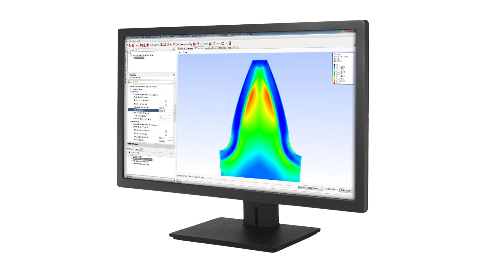
ホブ切り加工シミュレーション
この新しく改訂および更新されたモジュールは、ギアホブ切りの加工プロセスにおけるさまざまな静的エラーを考慮しています。プロセスシミュレーションモジュールは、製造条件下で偏差を含むギア形状を再現できます
電力損失/効率計算のためのメッシュ摩擦係数オプションの強化
以前の ISO/TR 14179-1:2001 法に加えて、新しい摩擦係数の計算方法が使用できるようになりました
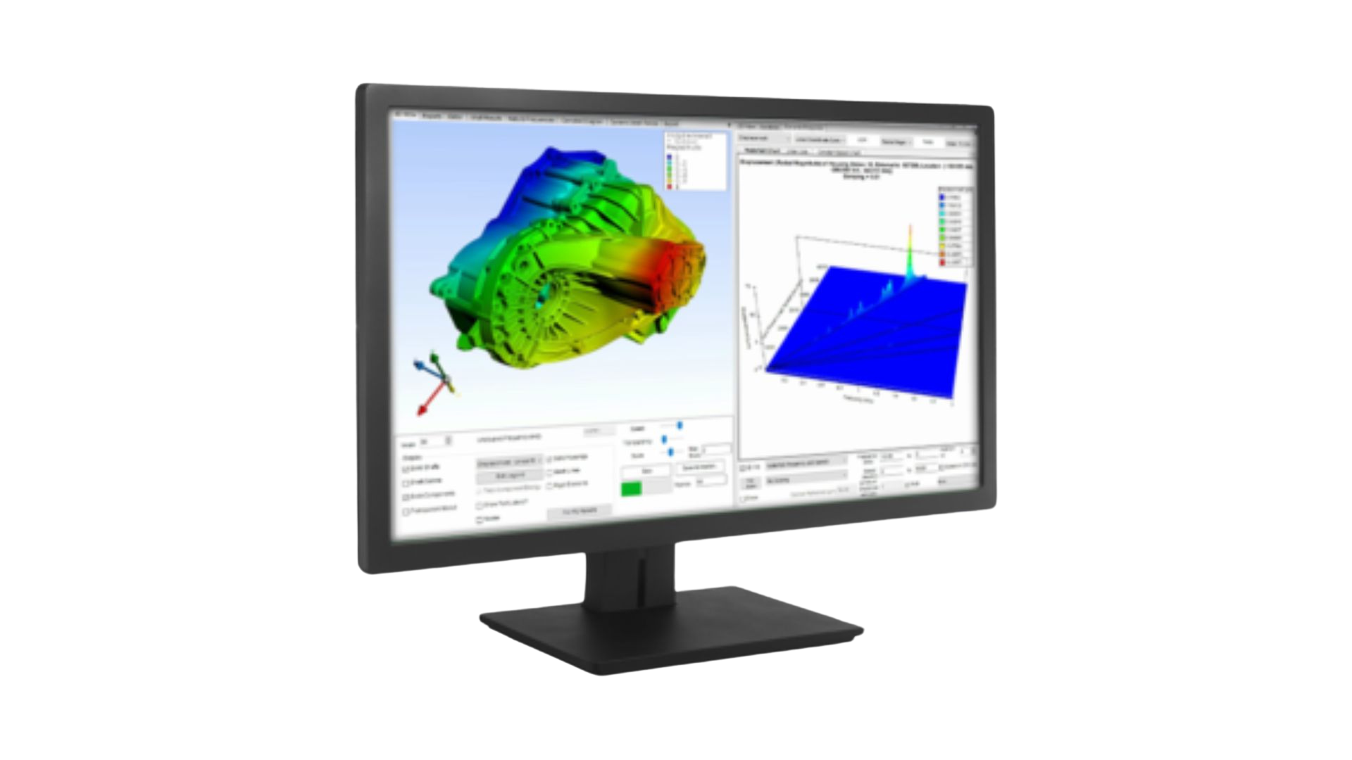
ギアフランクローディングインジケーター
ロードされたギアの側面を示します。Powerflowモードでは、逃げ面荷重を2Dビューと3Dビューの両方で視覚化できます。他のモードでは、このオプションは 2D ビューで使用できます
ISO計算された歯車の曲げ応力に対するショットピーニングの影響の包含
ISO 歯車材料の場合、材料がショット ピーニングされていることを指定し、歯車定格に含めるショット ピーニング曲げ応力の利点(Shot Peening Bending Stress Benefit)のパーセンテージを指定します
ギア公差基準
- AGMA 2101-D04に準拠した円筒歯車の定格を行う場合、既存のAGMA 2015-1-A01規格に加えて、AGMA 2000-A88およびANSI/AGMA ISO 1328-1-B14公差規格の使用を指定できるようになりました
- ISO 6336に準拠した円筒歯車の定格を行う際に、既存のISO 1328-1:1995(E)/ISO 1328-2:1997(E)規格に加えて、ISO 1328-1:2013(E)/ISO 1328-2:1997(E)公差規格の使用を指定できるようになりました
- 「公差丸めシステム」を「メートル法」または「インペリアル法」に選択することができます
ベベル/ハイポイドギアのミスアライメント
クロスポイントを基準にして計算された以前の結果に加えて、ギアの噛み合い点を基準にして計算されたミスアライメントのテーブルを含めます
CADレポートの改善
- CAD レポートは以前のリリースから強化され、CAD Gear Data Sheets にデータや情報を追加する機能が追加されました
- 設計/解析値を反映するように値が更新されるプロパティラベル付きの画像を含める
- CAD レポート テンプレートの指定
ローラーベアリングの改良
円筒ころ軸受の動的等価荷重計算に、推定係数に加えて軸方向荷重を受けることができるユーザー指定のX、Y係数を含めます。
LDP インポート
自民党から基本設計を取り入れる。この初期実装は、内部または外部の円筒歯車のペアに限定されており、現在インポートされているのはマクロ ジオメトリのみです。
FE コンポーネント ノード接続レポート
インポートされたFEコンポーネントの精度を評価するための補助として、接続されたコンポーネント上のFE節点の予想される位置と実際の位置を示す3つの新しいテーブルが設計モードのインポートされたFEコンポーネントのデフォルトレポートに含まれています
インポートされたFEとのベアリング節点のアライメント
軸受の FE 凝縮節点を軸受の中心に作成するか、軸受レースの中心に作成するかを指定します。これは、先すいころ軸受など、軸受のレースが必ずしも軸受の全幅ではない軸受に特に役立ちます
円筒歯車のミスアライメント計算方法
代替ミスアライメント定義に基づく円筒歯車のミスアライメント計算
LTCA計算値を使用したAGMA評価
[設定]の[円筒歯車定格]セクションの[AGMA定格]オプションの下部にあるオプションを選択して、マイクロ ジオメトリ モードで AGMA 2101-D04 に従って歯車定格を実行するときに LTCA 応力を使用します
溶接/構造要因
スカッフィング計算で使用される溶接/構造係数 Xw を指定する新しいオプション