Thanks for joining us again!
In Part 1 and 2 of this series of modal validation blog posts, we validated MASTA modelling of a singular gearbox half casing and casings bolted together against modal test data.
Our findings are available here:
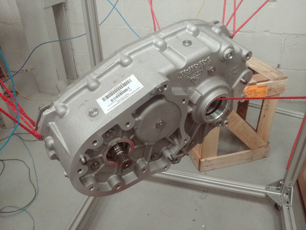
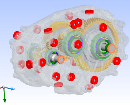
Part Three (this blog) expands on this research by including a full gearbox casing made of two separate halves bolted together, as well as gearbox internals of gears, shafts, and bearings.
Let Us Begin
Casings bolted together with internals test setup
Casings bolted together with internals MASTA model
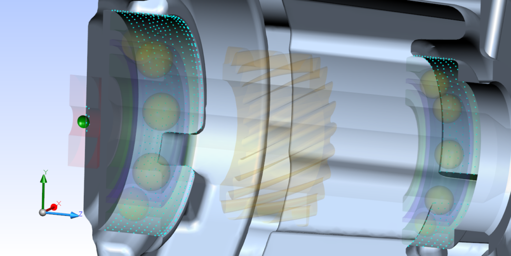
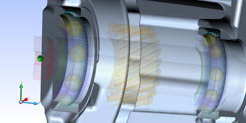
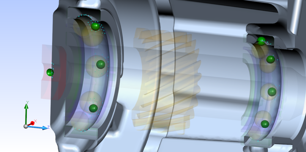
The connection of bearings to the FE casing can be considered with a single node at the centre of the bearing or a node ring with each node at a bearing element position.
The bearing ring may also be included in the casing FE to provide a more realistic node connection patch.
The bearings for this gearbox have a sliding fit on the shafts and a shrink fit in the casing, so we are determining the most accurate FE setup for this arrangement.
Condensation node setup with single node for bearing, single node for bearing with bearing ring included in FE, and ring of nodes for bearing with bearing ring in FE
What Did We Find?
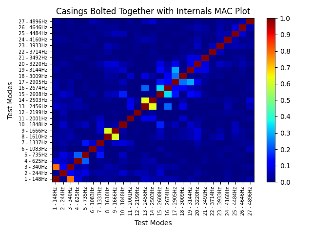
To validate the test, we found a small number of off-diagonal terms on each test vs itself MAC plot, indicating that enough accelerometer positions were used to find the full mode shapes in both tests.
MAC plot test versus itself for casings bolted together with internals
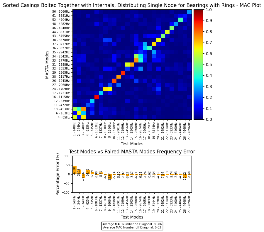
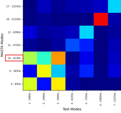
Test versus simulation MAC plots show very good correlation up to ~ 4 kHz, with correlation generally weakening as frequency is increased.
Frequency differences between modes are also mostly under 5%.
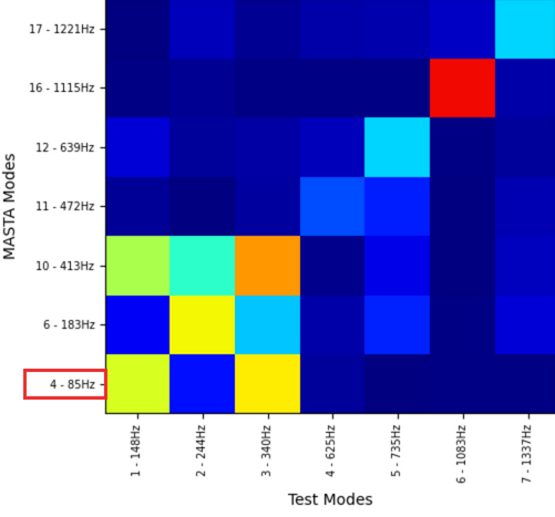
MAC plot test versus simulation for casings bolted together with internals
High frequency differences between modes are seen below 1 kHz; looking at the mode shapes, these lower frequency modes are effectively rigid body modes of the casing and so are less important for potential casing vibration when in operation.
This also explains why these modes have high MAC numbers in the MAC plot when compared to multiple test modes.
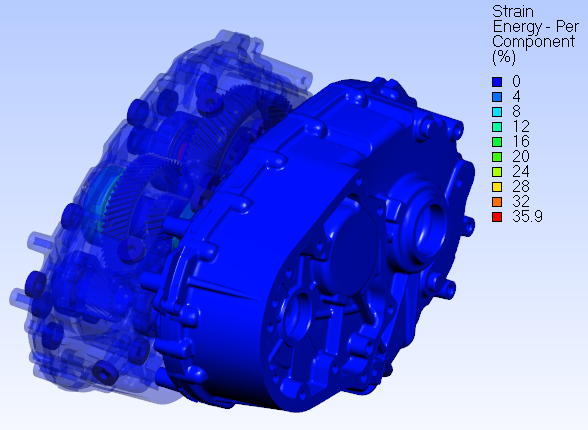
Casings bolted together with internals mode shape for mode 4
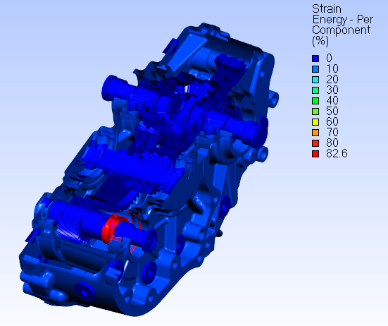
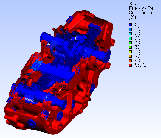
Casings bolted together with internals mode shape for mode 10
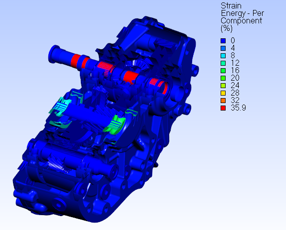
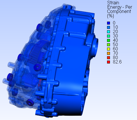
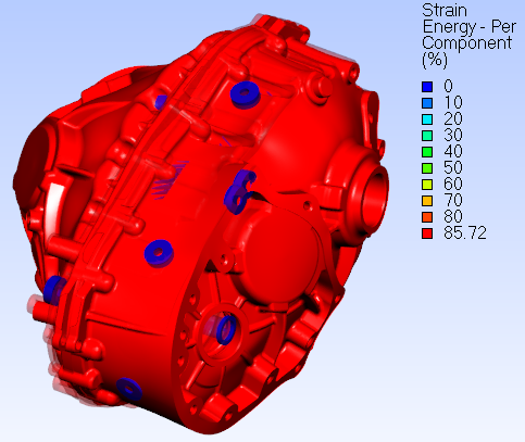
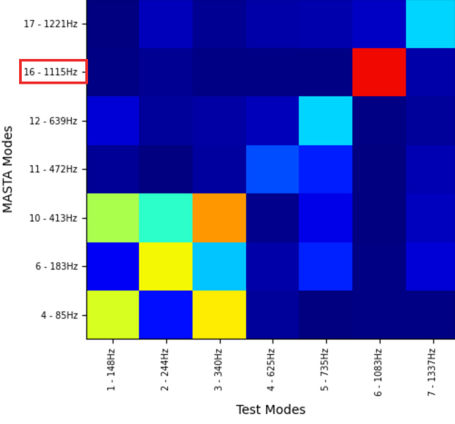
Below is an example of a mode with high strain energy in the casing and casing panel expansion, a more characteristic mode of the structure that will be important to model accurately when considering full vibration response from, for example, gear or motor excitation.
This mode has a high MAC number, indicating it was captured accurately.
Casings bolted together with internals mode shape for mode 16
We used the average MAC number on the diagonal to compare the various model setup changes to the FE model for the test vs simulation MAC plots,
- Including bearings rings in the casing FE made a noticeable improvement to the correlation
- Including node rings for the bearings made little difference to the modal correlation in the case of distributing couplings
- This is expected as distributing couplings will not affect the global stiffness of the structure
- Including node rings for the bearings made a noticeable improvement to the modal correlation in the case of kinematic couplings
| Distributing / Kinematic | Single Node / Node Ring | Bearing Rings Included in FE? | Average MAC on Diagonal |
| Distributing | Single Node | No | 0.43 |
| Distributing | Single Node | Yes | 0.51 |
| Distributing | Node Ring | Yes | 0.50 |
| Kinematic | Single Node | No | 0.39 |
| Kinematic | Single Node | Yes | 0.46 |
| Kinematic | Node Ring | Yes | 0.50 |
Average MAC numbers across diagonal for various bearing modelling changes
It should be noted that node rings will more accurately model the loads at each bearing element, so when considering harmonic analysis of gear whine for example this may still provide a route for improving model accuracy and/or correlation.
However, node rings can also make thermal and fitting effects more difficult to analyse, so they should not be used in all cases, and the increase in condensation nodes increases FE reduction times.
To Wrap Up
Following modal testing validation of a single gearbox casing half and casing halves bolted together in part 1 and part 2 of this blog post, this has been extended to include casings bolted together with internals of gears, shafts and bearings.
For all bearing modelling options, an average MAC number of greater than 0.4 across the leading diagonal was obtained up to 5 kHz, and modal frequency differences of less than 5% were seen for most modes.
If you’ve been inspired by this information, please contact us to learn more.

